Buscar este blog

jueves, 13 de noviembre de 2014

4.7 inch QF Mark IX & XII


Montaje naval británico 
4.7 inch QF Mark IX & XII


El montaje naval 4.7 inch QF Mark IX & XII se trataba de un cañón de 120 mm (4,7 pulgadas) y 45 calibres que sirvió para armar la mayoría de los destructores de la Royal Navy y de la Commonwealth durante la Segunda Guerra Mundial. El 4.7 inch QF Mk.IX era un montaje simple, gemelo en el CP Mk.XIV, instalado en la Clase A de destructores a partir de 1930 y en la mayoría de los destructores de la Clase R de 1942. Por su parte los Mk.XII se instalaron en montajes gemelos (CP Mk XIX) en los destructores de la Clase Tribal de 1936 y en la Clase J, K y N completados en 1938.

Estos montajes tenían una elevación máxima de 40º aunque todos los montajes gemelos CP Mk XIX tenían un propósito doble ya que estaban instalados en pedestales Fuze Setting Pedestals o Fuze Setting Trays que les permitía disparar contra objetivos aéreos en colaboración con un computador de control de tiro. Con esta elevación se podía atacar a objetivos aéreos que atacasen a otros buques cercanos. Las primeras experiencias en este sentido tuvieron lugar durante la campaña Noruega entre abril y junio de 1940.

Cada cañón era capaz de disparar 12 salvas por minuto, ratio logrado durante unas pruebas de artillería en 1930 (El HMS Basilisk logró un ratio de cinco disparos en 17 segundos). El Mk.XII disparaba un proyectil de 22´5 Kg y usaba un cartucho separado que se cargaban a través de una bandeja de carga instalada para tal fin. El alcance efectivo era de 15.520 metros y la velocidad de salida del proyectil era de 808 m/s. El conjunto estaba parcialmente protegido por un escudo blindado que cubría tres lados, dejando la parte posterior del cañón al descubierto y con un techo que sólo cubría la mitad de la parte posterior.

El 4.7 inch QF fue finalmente reemplazado en los destructores Clase Z en 1943 por el 4.5 inch QF. Estos nuevos montajes permitían una elevación máxima de 55º y además era capaz de disparar un proyectil más pesado que utilizado por el 4.7 inch QF Mk.IX y XII, aunque más ligero que el disparado por el 4.7 inch QF Mk.XI. Tras la guerra se exportaron a muchos países.

Montaje gemelo Mk. XII en el HMS Javelin

Fuentes:
CAMPBELL, J. “Naval Weapons of World War II. Naval Institute Press, 1985
HODGES, P. “Destroyer Weapons of World War 2” Conway Maritime Press, 1979
MARCH, E. British Destroyers: A History of Development, 1892-1953; Drawn by Admiralty Permission From Official Records & Returns, Ships' Covers & Building Plans.Seeley Service, 1966

English version

The mounting 4.7 inch naval QF Mark IX & XII was a tube of 120 mm (4.7 inches) and 45 caliber that was used to build most of the destroyers of the Royal Navy and Commonwealth during World War II. The 4.7 inch QF Mk.IX was a simple assembly, twin in the CP Mk.XIV installed in Class destroyers from 1930 and most of the R class destroyers of 1942. Meanwhile the Mk xii twin mounts were installed (CP Mk XIX) in the Tribal class destroyers of 1936 and the Class J, K and N completed in 1938.

These assemblies have a maximum elevation of 40 ° if all twins assemblies CP Mk XIX had a dual purpose since they were installed on pedestals Fuze Setting Pedestals or Fuze Setting Trays that allowed them to shoot at air targets in conjunction with a computer fire control. With this elevation could attack air targets from attacking other nearby ships. The first experiments in this direction took place during the Norwegian campaign in April-June 1940.

Each gun was capable of firing 12 salvos per minute ratio achieved during testing of artillery in 1930 (HMS Basilisk achieved a ratio of five shots in 17 seconds). The Mk.XII fired a 22.5 kg projectile and used a separate cartridge that is loaded through a load board installed for this purpose. The effective range was 15,520 meters and bullet exit velocity was 808 m/s. The whole was partially protected by an armored shield covering three sides, leaving the rear of the barrel into the open and with a roof covered only half of the back.

The 4.7 inch QF was finally replaced in Z class destroyers in 1943 by 4.5 inch QF. These new mounts allow a maximum elevation of 55° and it was able to fire a heavier projectile used by the 4.7 inch QF Mk.IX and XII, but lighter than the one triggered by the 4.7 inch QF Mk.XI. After the war, were exported to many countries.


Sources:
CAMPBELL, J. “Naval Weapons of World War II. Naval Institute Press, 1985
HODGES, P. “Destroyer Weapons of World War 2” Conway Maritime Press, 1979
MARCH, E. British Destroyers: A History of Development, 1892-1953; Drawn by Admiralty Permission From Official Records & Returns, Ships' Covers & Building Plans. Seeley Service, 1966

miércoles, 12 de noviembre de 2014

Torretas del Tiger II


Diseño de las torretas del 
PzKpfw VI Tiger II

Torreta Henschel

Cuando surgió el diseño del PzKpfw VI Tiger II también aparecieron dos diseños de torretas disponibles para el nuevo carro de combate pesado. Uno de ellos fue diseñado por Hneschel mientras que el otro lo fue por la empresa Porsche. Ambas empresas tan sólo se involucraron en su diseño recayendo la labor de su producción sobre la empresa Krupp. El modelo propuesto por Porche fue designado como P2-Turm del que fabricó un total de 60 con el absoluto convencimiento de que ganaría el contrato. Sin embargo el modelo elegido fue el de su rival Henschel con su diseño designado como H3-Turm. Entre otras razones para tal decisión fue la composición de cada una de ellas, el diseño de Porche utilizaba demasiado cobre en su fabricación.

En cuanto al diseño la torreta propuesta por Porsche ofrecía un frontal curvo en el mantalete mientras que la propuesta de Henschel optaba por uno totalmente vertical. El diseño curvo presentaba problemas cuando era impactada por proyectiles enemigos ya que desviaban el proyectil hacia otras partes del vehículo, al igual que sucediese con el mantalete del PzKpfw V Panther. En ambos casos el proyectil que impactaba en la parte inferior del mantalete era desviado hacia el techo del casco menos protegido pudiendo penetrarlo matando al conductor, o en el peor de los casos, también al radio-operador. El diseño curvo de la torreta también obligaba a crear un saliente recto en el lado izquierdo que servía para dar cabida a la cúpula del jefe del carro.

A pesar de que las torretas de Porsche no fueron aprobadas para su producción industrial las 60 que ya había sido fabricadas fueron utilizadas sobre los bastidores de serie del PzKpfw VI Tiger II.

Torreta Porche. Uno de los 3 Tiger II desruidos en Châteaudun, el 17 de agosto de 1944, cerca de la calle Kellerman, adscrito al 1. Kompanie del Panzer-Abteilung(Flk) 316

Fuentes:
JENTZ, T. “Kingtiger Heavy Tank, 1942-45 Osprey, 1993
JENTZ, T. “Germany's Tiger Tanks - Vk45 to Tiger II: Design, Production & ModificationsSchiffer Publishing, 1997

English version

When the design of the PzKpfw VI Tiger II also emerged there were two turrets designs available for the new heavy tank. One was designed by Hneschel while the other was by the company Porsche. Both companies were involved only in its design falling production work on the Krupp. Porche's proposed model was designated as P2-Turm which produced a total of 60 with the absolute conviction that he would win the contract. However, the model chosen was that of his opponent Henschel your designated H3-Turm design. One reason for this decision was the composition of each, Porche design used too much copper in their manufacture.

In the design proposed by Porsche turret featuring a curved front in mantalete while Henschel proposed opted for a fully upright. The curved design had problems when he was struck by enemy projectiles as the projectile deviated to other parts of the vehicle, as happen with the PzKpfw V Panther mantalete. In both cases the bullet impacted at the bottom of mantalete was diverted toward the ceiling of the helmet can penetrate less protected killing the driver, or in the worst case, also the radio operator. The curved design of the turret also required to create a straight ledge on the left side that served to accommodate the dome of the head carriage.

Although Porsche turrets were not approved for industrial output 60 which had been manufactured were used on serial racks PzKpfw VI Tiger II.


Those five completed turrets, ready to be mounted on Tiger II chassis, were still at Henschel when occupied by American forces in late March 1945. 

Sources:
JENTZ, T. “Kingtiger Heavy Tank, 1942-45 Osprey, 1993
JENTZ, T. “Germany's Tiger Tanks - Vk45 to Tiger II: Design, Production & ModificationsSchiffer Publishing, 1997

martes, 11 de noviembre de 2014

Cazacarros TACAM R-2

Cazacarros rumano TACAM R-2


El TACAM R-2 fue otro cazacarros rumano diseñado con el objetivo de superar la carencia de medios acorazados modernos durante la Segunda Guerra Mundial. En diciembre de 1942 el carro de combate ligero R-2 (designación rumana para los PzKpfw 35) había quedado obsoleto para operaciones en primera línea y se decidió transformarlos en cazacarros siguiendo la estela de la serie Marder II alemana y el TACAM T-60 de fabricación nacional, aún en desarrollo. Para el montaje del nuevo vehículo se eliminó la torreta del R-2 y el vehículo fue probado en el verano de 1943. Para armar a este nuevo cazacarros se utilizó inicialmente los cañones soviéticos capturados M-1936 M-22 de 76´2 mm que se instalaba en una caja blindada que protegía a la dotación por tres de sus lados. Estas cajas blindadas fueron construidas a partir de blindaje de otros vehículos soviéticos capturados BT-7 y T-26. Por su parte, el cañón, tuvo que ser modificado para que aceptase la munición de 75 mm rumana. Las pruebas finales del conjunto tuvieron lugar a finales de 1943, el cañón sólo era efectivo contra el T-34 a alcances de entre 600 y 500 metros mientras que el chasis del R-2 se mostró falto de potencia para su nuevo peso. A pesar de sus deficiencias se realizó un pedido inicial de 40 vehículos que debían ser servidos por la empresa Leonida en Bucarest. Se tenía pensado sustituir el R-2 por un vehículo con más prestaciones y también pasaría lo mismo con el arma principal que sería sustituida por el ZiS-3, en ambos casos serían los alemanes los que proporcionarían tanto los vehículos como los cañones. También se hicieron planes para armar el conjunto con cañones más potentes para poder enfrentarse a los carros de combate pesados soviéticos, como armarlos con cañones de 88 mm, pero no pasó de las mesas de diseño.

En cuanto al resultado final, el RACAM R-2, estuvo armado con un cañón ZiS-3 de 76´2 mm junto con una ametralladora ZB-53 de 7´92 mm para su defensa cercana. El escudo blindado que protegía a la dotación estaba parcialmente techado y tenía un blindaje de entre 10 y 17 mm de espesor. El cañón tenía un giro transversal de 30º, se podía elevar hasta 15º y una depresión de 5º. El arma principal tenía una dotación de 30 proyectiles (21 de alto explosivo y 9 perforantes). El bastidor del R-2 tuvo pocos cambios respecto al original. Tenía una capacidad de combustible de 153 litros que le permitían una autonomía de 130-160 Km a una velocidad máxima de 25-30 Km/h en carretera. 


Los trabajos sobre los R-2 comenzaron en febrero de 1944 terminando el primer lote de 20 vehículos a finales de junio. Sin embargo la producción se detuvo ya que el cañón M-1936 M-22 se mostró falto de potencia al enfrentarse con los medios acorazados pesados soviéticos. De los vehículos completados, 10 fueron encuadrados en la 63º Compañía TACAM en julio de 1944, asignada a la 1º División Acorazada de Entrenamiento. La unidad no entró en combate antes de que Rumanía abandonase el Eje para pasarse a los Aliados. Una compañía de 12 vehículos fueron encuadrados en el Destacamento Niculescu siendo enviado para defender la frontera de Transilvania contra un contraataque de las fuerzas del Eje estacionadas en Hungría. Otros 4 vehículos más llegaron a esa unidad el 29 de septiembre cuando se preparaban las operaciones para despejar el norte de Transilvania. Finalmente el grupo se disolvió cuando las fuerzas del Eje abandonaron el territorio rumano el 25 de octubre de 1944.

Otros 12 vehículos fueron asignados al 2º Regimiento Blindado y enviado al frente en Checoslovaquia en febrero de 1945. Los soviéticos se quedaron con los TACAM R-2 a cambio de un puñado de carros de combate alemanes capturados aunque al menos 2 TACAM R-2 quedaron en manos rumanas para el 24 de abril. Uno de ellos resultó destruido antes del día 30 y el otro quedó dañado cerca de Brno. Cuando el Regimiento regresó a Bucarest el 14 de mayo de 1945 ya no tenía ningún TACAM R-2 en su inventarío. Actualmente uno de ellos sobrevive en el Museo Nacional Militar de Bucarest. 

 Museo Nacional Militar de Bucarest.

Fuentes:
AXWORTHY, M. “Third Axis, Fourth Ally: Romanian Armed Forces in the European War, 1941-1945 Arms and Armour, 1995
KLIMENT, C. “Czechoslovak Armored Fighting Vehicles” Schiffer, 1997

English version

The R-2 TACAM another Romanian tank destroyer was designed with the aim of overcoming the lack of modern means battleships during World War II. In December 1942 the car light combat R-2 (Romanian designation for PzKpfw 35) had become obsolete for front line operations and decided to turn them into tank destroyers in the wake of the German Marder II series and the T-60 TACAM domestic, still developing. For installation of the new vehicle turret R-2 was removed and the vehicle was tested in the summer of 1943. To build this new Soviet tank destroyer guns captured was initially used M-1936 M-22 76.2 mm was installed in a shielded box that protected the crew from three sides. These armored boxes were constructed from other Soviet armor vehicles captured BT-7 and T-26. For its part, the barrel had to be modified to accept 75mm ammunition Romanian. Final testing of the assembly took place in late 1943, the cannon was only effective against the T-34 at ranges of 600 to 500 meters while the chassis of the R-2 was shown to lack power to your new weight. Despite its shortcomings an initial order for 40 vehicles which were to be served by the company took place in Bucharest Leonida. They had planned to replace the R-2 for a vehicle with more features and the same thing would happen with the main weapon would be replaced by the ZIS-3, both the Germans who would provide both vehicles and guns. There were also plans to build the set with more powerful cannons to confront the Soviet heavy tanks combat as arm them with 88mm guns, but did not go beyond the drawing boards.

As for the final result, RACAM R-2, was armed with a gun ZIS-3 76.2 mm along with a ZB-53 7.92 mm machine gun for close defense. The armored shield that protected the envelope was partially covered and had a vault of 10 to 17 mm thick. The gun had a transverse rotation of 30°, could raise up to 15° and a depression of 5°. The main gun had a crew of 30 rounds (21 and 9-piercing high explosive). The frame of the R-2 had few changes from the original. It had a fuel capacity of 153 liters which enabled a range of 130-160 km at a speed of 25-30 km/ h on the highway.


Work on the R-2 began in February 1944, ending the first batch of 20 vehicles at the end of June. But production was halted since the barrel M-1936 M-22 was underpowered to cope with the heavy armored Soviet media. Of completed vehicles, 10 were fitted in the 63rd TACAM Company in July 1944, assigned to the 1st Armored Division Training. The unit did not see combat before Romania to abandon the Axis in switching to the Allies. A company of 12 vehicles were framed in Niculescu Detachment being sent to defend the border of Transylvania against a counterattack by the Axis forces stationed in Hungary. 4 other vehicles over that unit came on 29 September when operations to clear northern Transylvania prepared. Eventually the group disbanded when the Axis forces left the Romanian territory October 25, 1944.

Another 12 vehicles were assigned to the 2nd Armored Regiment and sent to the front in Czechoslovakia in February 1945. The Soviets were left with TACAM R-2 in exchange for a handful of captured German tanks but at least 2 TACAM R-2 were in Romanian hands for April 24. One of them was destroyed by the 30 and the other was damaged near Brno. When the regiment returned to Bucharest on May 14, 1945 no longer had any TACAM R-2 in your inventory. Currently one survives in the National Military Museum in Bucharest.


Sources:
AXWORTHY, M. “Third Axis, Fourth Ally: Romanian Armed Forces in the European War, 1941-1945 Arms and Armour, 1995
KLIMENT, C. “Czechoslovak Armored Fighting Vehicles” Schiffer, 1997

viernes, 7 de noviembre de 2014

Munitionspanzer III


Munitionspanzer III


A partir de 1942 el papel del PzKpfw III comenzó a decaer en las unidades de primera línea al ser superado en cañón y blindaje por sus oponentes. El OKW pensó en un principio en producir un vehículo específico para el transporte de municiones y otros pertrechos a las unidades acorazadas de primera línea. Sin embargo para no entorpecer la presionada industria alemana se optó por transformar los vehículos que eran devueltos del frente con daños y que tenían posibilidades para su reparación.

Esta política también se extendió a la construcción de cañones de asalto (ya fuesen PzKpfw III o PzKpfw IV) y vehículos de apoyo, como por ejemplo para los ingenieros de asalto, recuperación o transporte de municiones. La modificación que nos ocupa era una de las más sencillas que se podían realizar sobre el bastidor de un PzKpfw III. Para ello se retiraba la torreta sellándose la placa giratoria con una escotilla o una tapa de lona. Fue en este punto dónde se produjeron más modificaciones de campaña por las mismas tripulaciones que los operaron.

En el interior se instalaron soportes adicionales para el transporte de munición y se mantuvo la ametralladora del frontal del casco para su autodefensa. También se mantuvo el equipo de radio para poder comunicarse con facilidad. Para compensar el aumento del peso del vehículo por la carga transportada muchos de estos vehículos estuvieron equipados con orugas Ostketten que aumentaba la superficie en contacto con el suelo disminuyendo la presión sobre el suelo. También hubo modelos provistos de blindaje lateral Schürzen. Fueron muchos los bastidores utilizados para su construcción pero los más usados provinieron del PzKpfw III Ausf G devueltos del frente.


Fuentes:
FLEISCHER, W. “Panzerkampfwagen III der Panzer der Blitzkriege” 2001
JERCHEL, M. “The Panzerkampfwagen III at war Concord. 1997
SPIELBERGER, W. “Der Panzerkampfwagen III und seine Abarten Motorbuch Verlag, 1984

English version

Since 1942 the role of the PzKpfw III began to decline in frontline units to be overcome in cannon and shield by his opponents. The OKW thought at first to produce a specific vehicle for transporting ammunition and other supplies to the frontline armored units. But to not hamper down German industry chose to transform the vehicles were returned from the front with damage and had chances for repair.

This policy also extended to the construction of assault guns (and PzKpfw III or PzKpfw IV were) and support vehicles, such as engineers for assault, recovery or transport of ammunition. The amendment in question was one of the simplest that could be performed on the frame of a PzKpfw III. This turret turntable being sealed with a lid or a hatch canvas retired. It was at this point where further modifications campaign for the same crews that operated occurred.

Additional supports inside settled for transporting ammunition and the gun of the front hull remained for self-defense. Radio equipment also continued to communicate with ease. To compensate for the increased weight of the vehicle for cargo transported many of these vehicles were equipped with caterpillar Ostketten which increased the surface area in contact with the soil, reducing the pressure on the ground. There were also models with side armor Schürzen. There were many racks used for construction but the most used came from PzKpfw III Ausf G returned from the front.


Sources:
FLEISCHER, W. “Panzerkampfwagen III der Panzer der Blitzkriege” 2001
JERCHEL, M. “The Panzerkampfwagen III at war Concord. 1997
SPIELBERGER, W. “Der Panzerkampfwagen III und seine Abarten Motorbuch Verlag, 1984

jueves, 6 de noviembre de 2014

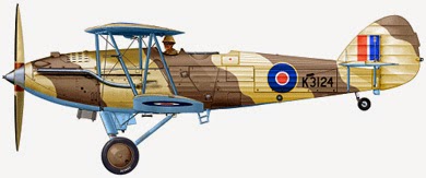
Hawker Audax


Hawker Audax


Tras la primeras experiencias de bombardeo diurno con el Hawker Hart quedó patente que los bombarderos tendrían que poder desempeñar una cierta variedad de roles en el campo de batalla moderno. El Ejército requería un aparato de cooperación que reemplazase los mediocres Armstrong Whitworth Atlas y Westland Wapiti. Los requisitos para el nuevo aparato surgieron en 1926, el bombardero ligero sería de construcción metálica, con una tripulación de dos hombres y una velocidad máxima de 258 Km/h. Al concurso participaron tres empresas, Hawker, Avro y de Havilland volando el primer prototipo de Hawker en junio de 1928. Finalmente sería el proyecto de Hawker el que se alzaría con el contrato.

El Audax podía alcanzar una velocidad máxima de 274 Km/h con una velocidad de crucero de 240 Km/h. Su techo de servicio era de 6.400 m y tenía una autonomía de 600 Km. Su armamento consistía en 2 o 4 ametralladoras de 7´7 mm y podía transportar hasta 250 Kg en bombas.

La RAF realizó un pedido inicial de 625 Hawker Audax, incluyendo los pedidos de Sudáfrica y los transferidos a Malasia para la Fuerza Aérea de Voluntarios. Otros aparatos fueron construidos por Persia, bajo el nombre Bristol Pegasus y motores Pratt & Whitney Hornet, Irak (52º Sqn.), Canadá, Singapur y Egipto (173º y 267º Sqn.). Estos últimos fueron proporcionados para la defensa de Egipto, el Sudán y la zona del Canal pero contaron con una motorización distinta. También fueron utilizados en Etiopía contra las fuerzas italianas en junio de 1940 con el 237º Sqn. Con la invasión japonesa de India en diciembre de 1941 dos escuadrones de Audax (5º y 146º Sqn.) fueron utilizados como aparatos de caza hasta la llegada de los cazas Curtiss Mohawk que los reemplazaron a principios de 1942.  El 28º Sqn. mantuvo algunos de sus Audax empleándolos en operaciones de ataque a tierra durante el avance japonés a Burma.

Los Audax sirvieron para dotar al 4º Sqn. en febrero de 1931 mientras que la producción se extendió hasta 1937 utilizando subcontratas con Bristol, Gloster, A.V.Roe y Westland. Algunos basados en el extranjero aún estaban en servicio en 1941 y 1942. Los últimos Squadrons equipados con Audax operativos en primera línea eran el 1º y 3º Sqn. de la Fuerza Aérea India. Estos aparatos estuvieron operativos hasta septiembre de 1943. Por su parte, el 1º Sqn., mantuvo sus Audax con su cometido original de ataque a tierra entre septiembre de 1943 y enero de 1944 (en Digboi en el noreste de Assam). El resto de aparatos fueron utilizados desde el inicio de la guerra como remolcadores de planeadores Hotspur, labores de comunicación y entrenadores mientras que 18 Audax fueron transformados en Hawker Hart especiales. Los Audax fueron sustituidos en el servicio por los Westland Lysander en 1937-38.


Fuentes:
CRAWFORD, A. “Hawker Hart Family Mushroom Model, 2008
THELFORD, O. “By Day and By Night: Hawker Hart and Hind: Operational History Part OneAeroplane Monthly, Vol. 24, 1995
LEWIS, P. “The British Bomber since 1914 Sixty Years of Design and Development.Putnam, 1974

English version

After the first daylight bombing experiences with Hawker Hart became clear that the bombers would have to play a certain variety of roles in the modern battlefield. The Army required a system of cooperation that would replace the mediocre Armstrong Whitworth Atlas and Westland Wapiti. The requirements for the new system came in 1926, would light bomber steel construction, with a crew of two men and a top speed of 258 Km/h. The competition involved three companies, Hawker, Avro and de Havilland flew the first prototype of Hawker in June 1928. Finally, the project would Hawker which would rise to the contract.

The Audax could reach a top speed of 274 km/h with a cruising speed of 240 Km/h. Its service ceiling was 6,400 m and had a range of 600 km. Its armament consisted of 2 or 4 7.7 mm machine guns and could carry up to 250 kg bombs.


The RAF conducted an initial order for 625 Hawker Audax, including orders from South Africa and those transferred to Malaysia for Air Force Volunteer. Other devices were built by Persia, under the name Bristol Pegasus and Pratt & Whitney Hornet, Iraq (52nd Sqn.), Canada, Singapore and Egypt (173º and 267º Sqn.). The latter were provided for the defense of Egypt, Sudan and the Canal Zone but told with a different engine. They were also used in Ethiopia against the Italian forces in June 1940 with 237º Sqn. With the Japanese invasion of India in December 1941, two squadrons of Audax (5th and 146th Sqn.) Were used as hunting equipment until the arrival of the Mohawk fighter Curtiss replaced in early 1942. The 28th Sqn. Audax kept some of its operations by employing them in ground attack during the Japanese advance into Burma.

The Audax served to give the 4th Sqn. in February 1931 while production continued until 1937 using subcontractors with Bristol, Gloster, AVRoe and Westland. Some based abroad were still in service in 1941 and 1942. The last operational Squadrons equipped with Audax in front were the 1st and 3rd Sqn. Indian Air Force. These devices were operational until September 1943. Meanwhile, the 1st Sqn., Maintained its original mission Audax its ground attack between September 1943 and January 1944 (Digboi in northeastern Assam). The remaining aircraft were used from the beginning of the war as glider tugs Hotspur, communication efforts and coaches while 18 were transformed into Audax Hawker Hart special. The Audax were replaced in service by the Westland Lysander in 1937-38.


Sources:
CRAWFORD, A. “Hawker Hart Family Mushroom Model, 2008
THELFORD, O. “By Day and By Night: Hawker Hart and Hind: Operational History Part OneAeroplane Monthly, Vol. 24, 1995
LEWIS, P. “The British Bomber since 1914 Sixty Years of Design and Development.Putnam, 1974

miércoles, 5 de noviembre de 2014

Mitsubishi A5M


Mitsubishi A5M


El Mitsubishi A5M surgió a partir de una especificación de la Armada Imperial japonesa emitida en 1934 para proporcionar un caza monoplaza que alcanzase una velocidad máxima de 350 Km/h, un objetivo casi inalcanzable en aquella época. El 4 de febrero de 1935 voló por primera vez el primer prototipo, el Ka-14, que alcanzó una velocidad máxima de 450 Km/h. A pesar de estas buenas cualidades el aparato tenía algunas deficiencias aerodinámicas que debían ser subsanadas. El ala de gaviota invertida fue sustituida por una ala de ajuste bajo monoplano convencional en el segundo prototipo. Este aparato estaba equipado por un motor radial Nakajima Kotobuki-1 2-KAI de 436 kW que obtuvo buenos resultados. Pronto se ordenó la producción a partir de este segundo prototipo bajo la designación Mitsubishi A5M1.

El siguiente modelo, el Mitsubishi A5M2a, era similar al anterior pero estaba equipado con un motor más potente, el Kotobuki-KAI-3 de 455kW. Por su parte el A5M2b se motorizó con un Kotobuki 3 de 477kW. Estos aparatos fueron los principales cazas japoneses durante la Guerra chino-japonesa. Dos aviones experimentales, A5M3, volaron con un motor Hispano-Suiza 12Xcrs pero la versión final del aparato, designado A5M4 fue la que alcanzó más producción. También se fabricó una versión para el entrenamiento que contaba con dos asientos en tándem bajo la designación A5M4-K.


Todos las versiones del A5M recibieron la designación aliada de “Claude” y se completaron un total de 788 aparatos en todas sus versiones en las factorías de Mitsubishi. Otros 303 aparatos se fabricaron por Watanabe y 264 por el Arsenal Aeronaval Omura. El Ejército japonés también mostró interés por este aparato evaluándose el prototipo Ki-18, en general similar al Ka-14, pero a pesar de su velocidad punta fue desechado para el Ejército al argumentar falta de maniobrabilidad. Mitsubishi finalizó dos prototipos (Ki-33) más que incorporaban mejoras en la planta motriz pero fueron también rechazados por la misma causa. El aparato, A5M4, estaba armado con dos ametralladoras de 7´7 mm y podía cargar con dos bombas de 30 Kg. La velocidad máxima quedó en 430 Km/h con un alcance de 1.200 Km.

Al estallar la guerra en el Pacífico el A5M4 estaba en uso en primera línea pero su rendimiento fue decayendo al enfrentarse con los cazas aliados más modernos que él. Para el verano de 1942 los aparatos supervivientes fueron trasladados a tareas de segunda línea. En los últimos meses de la guerra los A5M4 y A5M4-K supervivientes fueron usados para ataques kamikaze


Fuentes:
MONDEY, D. “Concise Guide to Axis Aircraft of World War II.” Temple Press, 1984
FRANCILLON, R.  Japanese Aircraft of the Pacific War” Putnam & Company, 1970
JANUSZEWSKI, T. “Mitsubishi A5M Claude” MMPBooks, 2013

English version

The Mitsubishi A5M arose from a specification of the Imperial Japanese Navy issued in 1934 to provide a car chase that reached a maximum speed of 350 km/h, an almost unattainable goal at the time. On February 4, 1935 first flew the first prototype, the Ka-14, which reached a top speed of 450 km/h. Despite these good qualities the unit had some aerodynamic deficiencies that needed to be remedied. The inverted gull wing was replaced by a conventional low-wing monoplane adjustment in the second prototype. This apparatus was equipped by a Nakajima Kotobuki radial engine-KAI-1 2 436 kW achieved good results. Soon production was ordered from the second prototype under the name Mitsubishi A5M1.

The following model, Mitsubishi A5M2a, was similar to the above but was equipped with a more powerful engine, Kotobuki-KAI-3 455kW. For his part A5M2b was motorized with Kotobuki 3 of 477kW. These devices were the main Japanese fighters during the Sino-Japanese War. Two experimental aircraft A5M3 flew a Hispano-Suiza engine 12Xcrs but the final version of the device, which was designated A5M4 reached more production. A version for training that had two tandem seats under the designation A5M4-K was also produced.

All versions A5M received the Allied designation of "Claude" and a total of 788 devices were completed in all their versions Mitsubishi factories. Other 303 aircraft by Watanabe and 264 manufactured by Aeronaval Omura Arsenal. The Japanese Army also showed interest in this unit assessed Ki-18, generally similar to the Ka-14, but despite his top speed was scrapped for the Army to argue lack of maneuverability prototype. Mitsubishi completed two prototypes (Ki-33) rather than incorporating improvements in the power plant but were also rejected for the same reason. The device, A5M4, was armed with two 7.7 mm machine guns and could carry two 30 kg bombs. The top speed was 430 km/h with a range of 1,200 km.

When the war in the Pacific the A5M4 was in use frontline but their performance was declining to confront modern Allied fighters than him. By the summer of 1942 the surviving aircraft were transferred to second line duties. In the last months of the war the A5M4 and A5M4-K survivors were used for kamikaze attacks.


Sources:
MONDEY, D. “Concise Guide to Axis Aircraft of World War II.” Temple Press, 1984
FRANCILLON, R.  Japanese Aircraft of the Pacific War” Putnam & Company, 1970
JANUSZEWSKI, T. “Mitsubishi A5M Claude” MMPBooks, 2013