domingo, 28 de diciembre de 2014

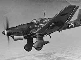
Junkers Ju 87 B-1

Junkers Ju 87 B-1 Stuka

Junkers Ju 87 B-1 "6G-HR" 4./StG-1. France, 1940


El Junkers Ju 87 B Stuka (Sturzkampfflugzeug, o bombardero en picado) constituyó la primera serie de este legendario bombardero en picado en ser producido en masa. Antes de comenzar con su producción se construyeron 6 prototipos denominados Ju 87 B-0 comenzando sus pruebas de vuelo en el verano de 1937 y posteriormente servirían como base para las versiones navales Ju 87 C y E.

El primer modelo de producción fue el Ju 87 B-1 que estaba equipado con un motor Junkers Jumo 211D de 1.184 hp de potencia. Este modelo introdujo un fuselaje y el tren de aterrizaje rediseñados. Los primeros aparatos en salir de la cadena de montaje fueron enviados a España para pruebas operativas dónde demostraron su eficacia como artillería volante. Tras estos éxitos iniciales la producción se incrementó hasta alcanzar los 60 aparatos al mes. Este aumento en la producción proporcionó 336 Junkers Ju 87 B-1 a las unidades de la Luftwaffe cuando estalló la Segunda Guerra Mundial. Estos aparatos estaban equipados con las famosas “Trompetas de Jericó”, unas sirenas instaladas en el borde de ataque de las alas, delante del tren de aterrizaje, o en el borde delantero del carenado principal. Estas sirenas, de 0´7 m de diámetro, eran accionadas por unas hélices y provocaban un aterrador sonido durante el picado que causaba el intimidación y pánico en las tropas enemigas. A lo largo de la contienda este efecto desapareció y las sirenas fueron retiradas ya que, además, provocaban la pérdida de entre 20 y 25 Km/h la velocidad punta debido a la resistencia de las mismas. La utilización del ruido en tal sentido continuó ya que algunas bombas eran equipadas con un silbato en la aleta que producía un ruido similar al ser lanzadas.

La producción del Ju 87 B-1 comenzó en julio de 1937; 89 fueron construidos en la fábrica de Junkers en Dessau junto con otros 40 más completados en Weserflug de Lemwerder. De esta última factoría se transfirió la producción a partir de abril de 1938, pero la producción del Ju 87 B-1 continuó hasta marzo de 1940. En total se completaron 697 Ju 87 B-1 (de ellos 311 fabricados por Junkers y 389 por Weserflug). El último de los Ju 87 B en salir de las cadenas de montaje lo hizo en octubre de 1940.


Fuentes:
MURAWSKI, M. J., “Junkers Ju 87, vol. I, II y III” Kagero, Monografie.
ERFURTH, H. “Junkers Ju 87 black cross”.
GRIEHL, M. “Junkers Ju 87 Stuka”. Airlife Publishing/Motorbuch, 2001
English version

The Junkers Ju 87 B Stuka (Sturzkampfflugzeug or dive bomber) was the first installment of this legendary dive bomber to be mass produced. Before beginning production in June prototypes called Ju 87 B-0 were built starting its flight testing in the summer of 1937 and then serve as a base for naval versions Ju 87 C and E.

The first production model was the Ju 87 B-1 was equipped with Junkers Jumo 211D engine of 1,184 hp. This model introduced a fuselage and landing gear redesigned. The first devices to come out of the assembly were sent to Spain for operational tests where they demonstrated their effectiveness as flying artillery. After these initial successes the production was increased to 60 devices per month. This increased production provided 336 Junkers Ju 87 B-1 units of the Luftwaffe at the outbreak of World War II. These devices were equipped with the famous "Trumpets of Jericho" sirens installed in the leading edge of the wings, landing gear front, or leading edge of the main enclosure. These mermaids, 0.7 m in diameter, were driven by a propeller and caused a terrifying sound during chopping the intimidation and causing panic in the enemy troops. Throughout this effect disappeared contention and sirens were removed and which also caused the loss of between 20 and 25 km/h the tip speed due to the strength thereof. The use of noise in this direction continued as some bombs were fitted with a whistle flap producing a noise similar to be released.

Production of the Ju 87 B-1 began in July 1937; 89 were built in the Junkers factory in Dessau with 40 more completed in Weserflug Lemwerder. This latest production factory from April 1938 was transferred, but production of the Ju 87 B-1 continued until March 1940. A total of 697 completed Ju 87 B-1 (of which 311 and 389 manufactured by Junkers Weserflug). The last of the Ju 87 B to leave the assembly lines did in October 1940.


Sources:
MURAWSKI, M. J., “Junkers Ju 87, vol. I, II y III” Kagero, Monografie.
ERFURTH, H. “Junkers Ju 87 black cross”.
GRIEHL, M. “Junkers Ju 87 Stuka”. Airlife Publishing/Motorbuch, 2001

viernes, 19 de diciembre de 2014

Northrop BT


Bombardero norteamericano
Northrop BT


El diseño del bombardero Northrop BT comenzó en 1935 con un prototipo para la Marina bajo la designación XFT-1. Este aparato, construido totalmente en metal, estaba propulsado por un motor radial Pratt and Whitney XR-1535-66 de 700 hp de potencia. También disponía de flaps perforados para el bombardeo en picado y un tren de aterrizaje semi retráctil que se plegaba hacia atrás sobre un carenado. Poco después se le dotó de un motor más potente, R-1535, de 750 hp. En 1936 apareció el BT-1 que estaba equipado con un motor radial R-1535-1594 de 825 hp de potencia. El tren de aterrizaje fue modificado dejándose fijo y se convirtió en la primera aeronave en aterrizar en un portaaviones.

La versión final del aparato, XBT-2, fue un BT-1 modificado para incorporar un tren de aterrizaje retráctil que se doblaba lateralmente y con una carlinga rediseñada. Estaba equipado con un motor radial Wright XR-1820-32 de 800 hp de potencia. el 25 de abril de 1938 realizó su primer vuelo y tras realizar un test de pruebas la Marina realizó un pedido inicial de 144 aparatos. En 1939 la designación fue cambiada recibiendo el nombre de Douglas SBD-1 completándose los últimos 87 aparatos como SBD-2. Este cambio fue debido a que Northrop Corporación pasó a ser parte integrante de Douglas.

El BT-1 tenía una tripulación de dos hombres y estaba armado con dos ametralladoras, una de 7´62 mm en tiro de caza y otra en su parte posterior de 12´7 mm para su autodefensa. Podía cargar con hasta 450 Kg en bombas bajo su fuselaje. Su velocidad máxima era de 357 Km/h con un techo de servicio de 7.710 metros. La US NAvy realizó un pedido de 54 BT-1 en 1936 que prestaron servicio a partir de 1938. Los BT-1 estuvieron destinados en los portaaviones USS Yorktown y USS Entreprise. Los BT-1 no tuvieron gran impacto debido a sus pobres prestaciones maniobreras y su baja velocidad. Un número significativo de aparatos se perdieron en accidentes. 


Fuentes:
BOWERS, P. “United States Navy Aircraft since 1911 Naval Institute Press, 1990
DRENDEL, L. “U.S. Navy Carrier Bombers of World War II Squadron/Signal Publications, 1987
LISTEMANN, P. “Northrop BT-1” (Allied Wings No.3). 2008
BRAZELTON, D. “The Douglas SBD Dauntless, Aircraft in Profile 196” Profile Publications Ltd., 1967

English version

The design of the bomber Northrop BT began in 1935 with a prototype for the Navy under the XFT-1 designation. This device, built entirely in metal, was powered by a Pratt and Whitney radial engine XR-1535-66 700 hp. Also available drilled for dive bombing and semi retractable landing gear train that folded back over a cowl flaps. Shortly after he was provided with a more powerful engine, R-1535, 750 hp. In 1936 showed that the BT-1 was equipped with a radial R-1535-1594 engine 825 hp. The landing gear was modified letting fixed and became the first aircraft to land on an aircraft carrier.

The final version of the device, XBT-2, BT-1 was modified to incorporate a retractable landing gear that was bent sideways and a redesigned cockpit. Was equipped with a radial engine 1820-1832 Wright XR-800 hp. the April 25, 1938 he made his first flight and after conducting a test of the Navy tests conducted an initial order for 144 devices. In 1939 the designation was changed receiving the name of Douglas SBD-1 completing the last 87 devices like SBD-2. This change was due to Northrop Corporation became an integral part of Douglas.

The BT-1 had a crew of two men and was armed with two machine guns, one of 7.62 mm in shooting game and another on the back of 12.7 mm for self-defense. It could carry up to 450 kg in bombs under the fuselage. Its top speed was 357 km/h with a service ceiling of 7710 meters. The US Navy placed an order for 54 BT-1 in 1936 who served from 1938. The BT-1 were stationed on aircraft carriers USS Enterprise and USS Yorktown. The BT-1 had no significant impact due to their poor performance and conniving low speed. A significant number of aircraft were lost in accidents.


 Northrop BT-1s over Miami in October 1939

Sources:
BOWERS, P. “United States Navy Aircraft since 1911 Naval Institute Press, 1990
DRENDEL, L. “U.S. Navy Carrier Bombers of World War II Squadron/Signal Publications, 1987
LISTEMANN, P. “Northrop BT-1” (Allied Wings No.3). 2008
BRAZELTON, D. “The Douglas SBD Dauntless, Aircraft in Profile 196” Profile Publications Ltd., 1967

miércoles, 17 de diciembre de 2014

Sd.Kfz 250/8


Sd.Kfz 250/8 Leichter Schützenpanzerwagen
(75 mm KwK 37)


El Sd.Kfz 250/8 fue producido para proporcionar apoyo de fuego cercano siendo equipado con los cañones KwK 37 de 75 mm excedentes de los PzKpfw IV Ausf E y Ausf F. Tan sólo un pequeño número fue construido utilizando el bastidor Alte introduciéndose en el servicio activo en la primavera de 1943. Otro lote fue construido en octubre de 1944 pero utilizando el nuevo bastidor (Neue). Estos vehículos fueron destinados a equipar al 4º Pelotón de los Leichter Panzer Aufklaerungs (Reconocimiento blindado ligero) de cada compañía.

El vehículo tenía un peso de 6.300 Kg y una tripulación de 3 o cuatro hombres. Tenía un motor Maybach HL42TRKM de 100 hp de potencia que le permitía alcanzar una velocidad máxima en carretera de 60 Km/h y una autonomía de 320 Km. Estaba armado con un cañón KwK 37 L/24 de 75 mm y una ametralladora MG 34 de 7´92 mm para su autodefensa en las primeras versiones. En las versiones posteriores el cañón fue sustituido por el K51 L/24 del mismo calibre junto con una ametralladora MG 34 de 7´92 mm. En ambos casos el vehículo era capaz de transportar hasta 20 proyectiles para el armamento principal. En cuanto al blindaje, oscilaba entre los 6 y los 14´5 mm de espesor. 


La composición teórica del batallón de reconocimiento alemán en 1944 incluía 4 compañías. La 2º y 3º Compañía de Reconocimiento estaban también equipadas con semiorugas de la serie 250. Cada una comprendía una plana mayor de compañía, tres secciones de reconocimiento y una sección de armas pesadas. El pelotón de plana mayor constaba de dos vehículos de radio SdKfz 250/3 de enlace, y una sección de reconocimiento tenía 7 transportes acorazados SdKfz 250/1, subdivididos en un vehículo de plana mayor de sección y tres pelotones de dos vehículos cada uno. La sección de armas pesadas consistía en un 250/1 en la plana mayor de la sección, un pelotón de apoyo cercano con dos obuses autopropulsados L/24 de 75 mm, SdKfz 250/8, y un TAP SdKfz 250/1, y un pelotón de morteros con dos transportes de mortero de 80 mm SdKfz 250/7 y un TAP 250/1.

La 4º Compañía Pesada comprendía, entre otros componentes, una sección de apoyo cercano constaba nominalmente de 6 obuses autopropulsados L/24 de 75 mm (SdKfz 250/9), y la sección de morteros, de 6 transportes de mortero de 80 mm SdKfz 251/2, pero en la prácitca se utilizaban con frecuencia el SdKfz 250/8 y el SdKfz 250/7.


Fuentes:
PERRET, B. “Autoametralladoras alemanas.
Osprey
KÖGEL, M. “Total Detail SdKfz 250 Alt - Neu Archive Part 2". Total Detail publications Ltd.
FORTY, J. “Sdkfz 250/1 To 250/12 Armoured Halftrack”, Miltary Vehicles in Detail 1
UWE F. & RIEGER, K. “Schützenpanzerwagen. Squadron/Signal.
De SISTO, F. “German Half-Tracks Of World War Two (Concord series #976)
LEDWOCH, J. “SdKfz 250 Wydawnictwo Militaria Nº019
GANDER, T. “Sdkfz 250/1 To 250/12 Armoured Halftrack (Miltary Vehicles in Detail 1) Ian Allan Publishing, 2006

English version

The Sd.Kfz 250/8 was produced to provide close fire support being fitted with the KwK 37 75mm guns surpluses PzKpfw IV Ausf E and Ausf F. Only a small number were built using the frame Alte introduced in service active in the spring of 1943. Another batch was built in October 1944 but using the new frame (Neue). These vehicles were intended to equip the 4th Platoon of Panzer Aufklaerungs Leichter (Light Armoured Reconnaissance) of each company.

The vehicle had a weight of 6,300 kg and a crew of three or four men. HL42TRKM had a Maybach engine power 100 hp allowing it to reach a maximum road speed of 60 km / h and a range of 320 km. It was armed with a cannon KwK 37 L/24 75mm gun and an MG 34 7 '92 mm for self-defense in the first versions. In later versions the barrel was replaced by K51 L/24 of the same caliber with an MG 34 machine gun 7.92 mm. In both cases the vehicle was able to carry up to 20 rounds for the main armament. As for the armor, ranged from 6 to 14.5 mm thick.

The theoretical composition of German reconnaissance battalion in 1944 included 4 companies. The 2nd and 3rd Reconnaissance Company were also equipped with half-tracks of the 250. Each series included a company's staff of three sections and a section reconnaissance heavy weapons. The squad consisted of two flat major vehicle SdKfz 250/3 radio link and a recognition section was 7 SdKfz 250/1 armored carriers, subdivided into a vehicle larger flat section and three platoons of two vehicles each. The section consisted of a heavy weapons a 250/1 on the staff of the section, close support platoon with two self-propelled howitzers L/24 75mm SdKfz 250/8 and SdKfz 250/1 TAP, and mortar platoon transports two 80 mm mortar SdKfz 250/7 and 250/1 TAP.

The 4th Heavy Company included, among other components, a close support section consisted nominally 6 self-propelled howitzers L/24 75mm (SdKfz 250/9) and the mortar platoon of 6 transport 80 mm mortar SdKfz 251/2, but in prácitca were often used the SdKfz 250/8 and SdKfz 250/7.


Sources:
PERRET, B. “Autoametralladoras alemanas. Osprey
KÖGEL, M. “Total Detail SdKfz 250 Alt - Neu Archive Part 2". Total Detail publications Ltd.
FORTY, J. “Sdkfz 250/1 To 250/12 Armoured Halftrack”, Miltary Vehicles in Detail 1
UWE F. & RIEGER, K. “Schützenpanzerwagen. Squadron/Signal.
De SISTO, F. “German Half-Tracks Of World War Two (Concord series #976)
LEDWOCH, J. “SdKfz 250 Wydawnictwo Militaria Nº019
GANDER, T. “Sdkfz 250/1 To 250/12 Armoured Halftrack (Miltary Vehicles in Detail 1) Ian Allan Publishing, 2006

martes, 16 de diciembre de 2014

Churchill: Diseño


Carro de combate pesado Churchill: Diseño


El carro de combate pesado Churchill recibió su nombre en honor al Primer Ministro británico, Winston Churchill. El bastidor se diseñó mediante planchas de acero unidas con pernos aunque posteriormente se optó por un método de soldaduras, más resistente. El casco tenía una distribución clásica con el puesto de conducción al frente, cámara de combate con la torreta sobre ella y la cámara del motor. La suspensión del vehículo estaba instalada bajo dos grandes cestas a ambos lados del casco con 11 ruedas de rodaje por lado aunque tan solo 9 de estas ruedas soportaban el peso del vehículo. La rueda delantera ayudaba a superar zanjas y trincheras mientras que la trasera servía de tensora para las orugas. Al disponer de tantas ruedas de rodadura el vehículo podía perder varias de ellas sin comprometer su movilidad. Para acceder al conjunto la cesta disponía de varias escotillas.

El Churchill disponía de dos motores Bedford conectados a través de un cigüeñal común que movía una transmisión regenerativa, la cual viraba el carro mediante una barra pausadora en lugar de palancas. El Churchill fue el primer carro de combate en emplear la caja de cambios Merritt-Brown, que permitía virar el tanque al cambiar la velocidad relativa de ambas orugas. Las primeras torretas eran redondeadas debido al sistema de su fabricación y de un tamaño más que suficiente como para albergar el cañón de 40 mm. Debido a su misión en el campo de batalla, apoyo a la infantería, los primeros vehículos estaban equipados con un obús instalado en el casco en una disposición similar al Char B1 francés. Esto limitaba su actuación ya que se tenía que girar el vehículo entero para apuntar el cañón instalado en el casco. El Churchill Mk II sustituyó el cañón del casco por una ametralladora mientras que en el Churchill Mk III sustituiría, además, el cañón de 40 mm por uno más potente de 57 mm. Se produjeron también algunas conversiones de campaña como por ejemplo en el norte de África. Fue en este escenario dónde algunos Churchill fueron armados con los cañones de 75 mm de los Sherman destruidos en combate. Estos vehículos extendieron su uso, bajo la denominación NA75, en la campaña de Italia en 1943. Ante los buenos resultados obtenidos por esta nueva configuración las versiones posteriores fueron equipadas con un cañón de 75 mm.


El punto fuerte del carro de combate Churchill fue su blindaje que alcanzaba un espesor máximo de 102 mm en el frontal, mientras que el mínimo era de 16 mm. Este grueso blindaje fue aumentado en el Churchill Mk VII con un máximo de 152 mm y un mínimo de 25 mm. A pesar de este espesor su blindaje no era muy efectivo ya que no estaba inclinado. A los vehículos supervivientes de las primeras versiones se les aumentó el blindaje mediante la soldadura de otras planchas encima. Al aumentar el blindaje también se incrementó el peso del vehículo sin embargo la planta motriz no fue modernizada con lo que las nuevas versiones resultaron más lentas. El Churchill Mk I alcanzaba un peso de 3.9118 kg mientras que en el Mk VII era de 4.0643 kg. La velocidad cayó desde los 26 Km/h hasta los 20 Km/h mientras que los motores fueron foco constante de problemas mecánicos por falta de potencia.

En cuanto a su armamento principal y a pesar de que el cañón de 75 mm tenía una potencia razonable, este no podía ser mejorado ya que la torreta resultaba muy pequeña para un cañón de mayo calibre. Su blindaje le proporcionaba una supervivencia más que razonable, incluso para soportar varios impactos del Flak 18 de 88 mm. Sin embargo su cañón no ofrecía la potencia de fuego necesaria para responder al fuego enemigo. En el tramo final de la contienda el Churchill fue superado en armamento por los cañones alemanes.

 Churchill IV NA75

Fuentes:
CHANT, C. “An Illustrated Data Guide to Battle Tanks of World War II
DELAFORCE, P. “Churchill's Secret Weapons: the story of Hobart's Funnies Pen & Sword, 2006
PERRET, B. “Churchill Infantry Tank 1941-1945” Osprey, 1993
FLETCHER, D. “The Great Tank Scandal: British Armour in the Second World War1989

English version

The heavy tank Churchill was named after the British Prime Minister, Winston Churchill. The frame was designed using steel plates bolted but later opted for a method of welding, tougher. The town had a classical distribution with the cockpit in front, combat camera with turret on it and the engine compartment. The vehicle suspension was installed in two large baskets on both sides of the hull with 11 wheels per side while shooting only 9 of these wheels support the weight of the vehicle. The front wheel helped to overcome ditches and trenches while the rear idler served for caterpillars. By having so many wheels rolling the vehicle could lose several of them without compromising mobility. To access all shopping had several hatches.

Churchill Bedford had two motors connected through a common crankshaft moving a regenerative transmission, which the car veered by bar instead of levers. The Churchill was the first chariot in using the gearbox Merritt-Brown, turn allowing the tank to change the relative speed of both tracks. The first towers were rounded due to manufacturing system and more than enough to accommodate the barrel 40 mm size. Because of its mission in the battlefield, infantry support, the first vehicles were equipped with a shell installed in the hull in a similar French Char B1 available. This limited their performance as they had to turn the entire vehicle to aim the cannon installed in the hull. The Churchill Mk II replaced the barrel of a machine gun helmet while on the Churchill Mk III also replace the 40 mm cannon with a more powerful 57 mm. Some conversions campaign also produced such as in North Africa. It was in this scenario where some Churchill were armed with 75mm guns of Sherman destroyed in combat. These vehicles extended use, under the name NA75 in the Italian campaign in 1943. Given the good results obtained by this new configuration later versions were equipped with 75 mm cannon.

The strong point of the tank Churchill was his shield reaching a maximum thickness of 102 mm on the front, while the minimum was 16 mm. This thick armor was increased in the Churchill Mk VII with a maximum of 152 mm and a minimum of 25 mm. Despite this his armor thickness was not very effective as it was not tilted. A surviving vehicles early versions were increased by welding shield other plates above. By increasing the armor vehicle weight but not the power plant was modernized with new versions were slower was also increased. Churchill Mk I reached a weight of 3.9118 kg while the Mk VII was of 4.0643 kg. The rate fell from 26 km/h to 20 km/h while the engines were constant focus of mechanical problems due to lack of power.

Regarding its main armament and despite the 75 mm gun had a reasonable power, this could not be improved because the turret was very small for a cannon caliber May. Its armor gave him a more than reasonable survival even to support various impacts of Flak 18 88 mm. However his cannon did not provide the firepower necessary to respond to enemy fire. Towards the end of the war Churchill was surpassed in arms by the German guns.


Sources:
CHANT, C. “An Illustrated Data Guide to Battle Tanks of World War II
DELAFORCE, P. “Churchill's Secret Weapons: the story of Hobart's Funnies Pen & Sword, 2006
PERRET, B. “Churchill Infantry Tank 1941-1945” Osprey, 1993
FLETCHER, D. “The Great Tank Scandal: British Armour in the Second World War1989

viernes, 12 de diciembre de 2014

Lanzacohetes Nebelwerfer 41


Lanzacohetes alemán
15 cm Nebelwerfer 41


El lanzacohetes Nebelwerfer 41 de 15 cm (15 cm NbW 41) fue ampliamente utilizado durante la contienda, encuadrados dentro de las unidades Nebeltruppen. Estas unidades estaban encargadas de las armas de gas y humo, de hecho, Nebelwerfer se traduce como “lanzador de humo”. Este lanzacohetes entró en servicio a partir de 1942 permaneciendo en acción hasta el final de la guerra.

El desarrollo del uso de los cohetes en el campo de batalla comenzó en 1920, pronto se vieron sus cualidades sobre todo para extender grandes cortinas de humo o ataques de gas al estilo de la Gran Guerra. En 1940 se entregaron las primeras unidades de 15 cm NbW 41, tras la batalla de Francia. Para mejorar su precisión los cohetes estaban estabilizados. Una característica muy inusual era que el motor de cohete estaba en la parte delantera con el objetivo de optimizar el efecto de la explosión y la fragmentación del cohete ya que como la ojiva todavía estaría por encima de la suelo cuando detonase aumentaría su poder destructivo. A pesar de este diseño tan innovador su fabricación resultaba complicada y no se perpetuó en los modelos siguientes.

El lanzador, de seis tubos, se montaba sobre el armón de los cañones anticarro PaK 36 de 37 mm adaptado. El conjunto alcanzaba un peso de 1.130 Kg con una tripulación de 5 hombres. El proyectil tenía un alcance máximo de 2.200 metros con una velocidad inicial de 145 metros por segundo. En total se fabricaron 5.283 lanzadores 15 cm NbW 41 y casi cinco millones de cohetes de 15 cm. 


Fuentes:
ENGLEMANN, J. “German Rocket Launchers in WWIISchiffer Publishing, 1990
ENGLEMANN, J. “Deutsche Artillerie 1934-1945: Eine Dokumentation in Text, Skizzen und Bildern: Ausrüstung, Gliderung, Ausbildung, Führung, Einsatz. Starke, 1974

English version

The Nebelwerfer 41 rocket 15 cm (15 cm NBW 41) was used extensively during the war, framed within Nebeltruppen units. These units were in charge of weapons of gas and smoke, in fact, Nebelwerfer translates as "smoke launcher". This rocket launcher entered service from 1942 remained in action until the end of the war.

The development of rocketry in the field began in 1920, soon his qualities especially were to extend large curtains of smoke or gas attacks in the style of the Great War. In 1940 the first units of 15 41 cm NBW surrendered after the Battle of France. To improve accuracy rockets were stabilized. A very unusual feature was that the rocket engine was in the front with the aim of optimizing the effect of the explosion and fragmentation rocket because as the warhead would still be above the ground when detonated increase its destructive power. Despite this innovative design and manufacturing was complicated not perpetuated in the following models.

The launcher, six tubes are mounted on
carriage of PaK 36 anti-tank guns of 37 mm adapted. The group reached a weight of 1,130 kg with a crew of 5 men. The missile had a maximum range of 2200 meters with an initial velocity of 145 meters per second. In total 5,283 launchers 15 cm NBW 41 and nearly five million 15cm rockets were manufactured.


Sources:
ENGLEMANN, J. “German Rocket Launchers in WWIISchiffer Publishing, 1990
ENGLEMANN, J. “Deutsche Artillerie 1934-1945: Eine Dokumentation in Text, Skizzen und Bildern: Ausrüstung, Gliderung, Ausbildung, Führung, Einsatz. Starke, 1974